9.1.3 Doppler Sodar
Commercial
sodars operated for the purpose of collecting upper-air wind measurements consist of antennas that transmit and receive
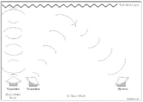
acoustic signals. A mono-static system uses the same antenna for
transmitting and receiving, while a bi-static system uses separate antennas.
The difference between the two antenna systems determines whether
atmospheric scattering by temperature fluctuations (in mono-static systems),
or by both temperature and wind velocity fluctuations (in bi-static systems)
is the basis of the measurement. The vast majority of sodars in use are of
the mono-static variety due to their more compact antenna size, simpler
operation, and

Figure 9-2 Simple depiction of a monostatic and bistatic sodar.
generally
greater altitude coverage. Figure 9-2 shows the beam configurations of
mono-static and bi-static systems.
Mono-static antenna systems can be divided into two categories: those using
multiple axis, individual antennas and those using a single phased-array
antenna. The multiple-axis systems
generally use three individual antennas aimed in specific directions to
steer the acoustic beam. One antenna is
generally aimed vertically, and the other two are tilted slightly from the vertical at an orthogonal angle. Each of the
individual antennas may use a single transducer focused
into a parabolic dish, or an array of speaker drivers and horns
(transducers) all transmitting in-phase
to form a single beam. Both the tilt angle from the vertical and the azimuth angle of each antenna need to be measured when
the system is set up. Phased-array antenna systems
use a single array of speaker drivers and horns (transducers), and the beams
are electronically steered by phasing the
transducers appropriately. To set up a phased-array antenna, one
needs to measure the pointing direction of the array and ensure that the
antenna is either level or oriented as
specified by the manufacturer.
The
horizontal components of the wind velocity are calculated from the radially
measured Doppler shifts and the specified tilt angle from the vertical. The
tilt angle, or zenith angle, is generally
1 5° to 3 0 °,
and the horizontal beams are typically oriented at right angles to one another. Since the Doppler shift of the radial
components along the tilted beams includes the influence
of both the horizontal and vertical components of the wind, a correction for
the vertical velocity should be applied
in systems with zenith angles less than 2 0 °.
In addition, if the system is located in
a region where expected vertical velocities may be greater than about 0.2 ms
-1 , corrections for the vertical
velocity should be made regardless of the beam's zenith angle. The
vertical range of sodars is approximately 0.2 to 2 kilometers (km) and is a
function of frequency, power output,
atmospheric stability, turbulence, and, most importantly, the noise environment
in which a sodar is operated. Operating frequencies range from less than
1000 Hz to over 4000 Hz, with power
levels up to several hundred watts. Due to the attenuation characteristics
of the atmosphere, high power, lower frequency sodars will generally produce greater height coverage. Some sodars can be
operated in different modes to better match vertical resolution
and range to the application. This is accomplished through a relaxation
between pulse length and maximum
altitude, as explained in Section 9.1.4 for radar wind profilers.
Sodar
systems should include available options for maximizing the intended
capabilities (e.g., altitude range,
sampling resolution, averaging time) of the system and for processing and validating the data. The selection of
installation site(s) should be made in consultation with the manufacturer
and should consider issues associated with the operation of the sodar
instrument. Training should be obtained
from the manufacturer on the installation, operation, maintenance, and data
validation. Additional information on these issues is provided in Section
9.5 of this document.
9. UPPER-AIR MONITORING
9.1 Fundamentals
9.1.1 Upper-Air Meteorological Variables
9.1.2 Radiosonde Sounding System
9.1.3 Doppler Sodar
9.1.4 Radar Wind Profiler
9.1.5 RASS
9.2 Performance Characteristics
9.2.1 Definition of Performance Specifications
9.2.2 Performance Characteristics of Radiosonde Sounding Systems
9.2.3 Performance Characteristics of Remote Sensing Systems
9.3 Monitoring Objectives and Goals
9.3.1 Data Quality Objectives
9.4 Siting and Exposure
9.5 Installation and Acceptance Testing
9.6 Quality Assurance and Quality Control
9.6.1 Calibration Methods
9.6.2 System and Performance Audits
9.6.3 Standard Operating Procedures
9.6.4 Operational Checks and Preventive Maintenance
9.6.5 Corrective Action and Reporting
9.6.6 Common Problems Encountered in Upper-Air Data Collection
9.7 Data Processing and Management (DP&M)
9.7.1 Overview of Data Products
9.7.2 Steps in DP&M
9.7.3 Data Archiving
9.8 Recommendations for Upper-Air Data Collection


